Ultrasonic IGBT Substrate Welding Equipment 20 kHz · 3000 W · Dual Station
Purpose-built cell for IGBT and power-module substrates – dual workstations, CCD position correction, X/Y/Z servo axes and multi-stage pressure profiles.

Precision bonding for power electronics
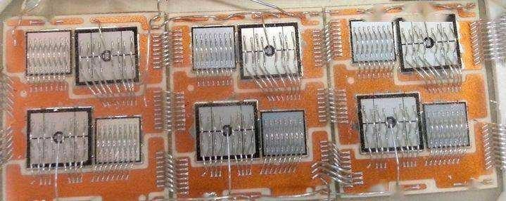
IGBT module terminals are thin, plated and unforgiving. This cell welds them with a CCD-corrected position loop: the camera finds the substrate fiducials, the X/Y/Z servo axes correct the tooling, and the multi-stage pressure profile lands the bond without cracking the ceramic.
Two stations alternate — welding runs while the operator loads the other side — so the machine keeps a duty cycle no single-station bench can match.


What happens in one cycle
Vision-guided alignment, staged force, logged result — every terminal, every time.
Load & vision
Operator loads a substrate; the CCD locates fiducials and measures offset.
Servo correction
X/Y/Z axes reposition the welding head to the corrected coordinates.
Staged weld
Pressure ramps through the profile while ultrasonics run 0.05–9.99 s or the set energy.
Log & unload
Result data writes to the 16 G controller store; the second station welds meanwhile.
Dust extraction is built in — plated terminals stay clean through the shift.
What the cell controls
| Control axis | Specification | Why it matters |
|---|---|---|
| Vision (CCD) | Fiducial-based position correction | Compensates substrate printing and nest tolerances |
| X / Y / Z servo | Programmable axes | Repeatable head placement across part variants |
| Pressure profile | Multi-stage ramp | Protects ceramics while achieving bond strength |
| Weld control | Time 0.05–9.99 s / energy 0.1–30 000 J | Mode per terminal design |
| Data | In-house controller, RS485 + USB, 16 G storage | Full trace per weld for quality files |
Technical specification
Tooling for your module family — horn and nest sets per substrate — is designed with the trial data.
Qualification path
Send substrates or the module drawings.
We bond-test and build the pressure profile.
FAT with your parts before shipment.
The 16 G store holds every weld’s parameters and curves for your quality records.
| Frequency | 20 kHz |
|---|---|
| Power | 3000 W |
| Working stroke | 50 mm |
| Stations | 2 (welding + loading/unloading) |
| Positioning | CCD correction + X/Y/Z servo |
| Weld time | 0.05–9.99 s |
| Energy mode | 0.1–30,000 J |
| Control | In-house controller, RS485 + USB, 16 G storage |
| Dimensions | 1320 × 1470 × 1620 mm |
| Weight | ≈800 kg |
| Power supply | 220 V ±10% |
Power-module lines it serves

IGBT Modules
Terminal bonding on power modules for drives and inverters.
Substrate Terminals
Clean, void-free bonds on plated thin terminals.
Batch Qualification
First-article batches welded and documented for customer sign-off.
Pair with

Generators (2000C / 2000E / H20)
Digital generators with auto frequency tracking — sized to the welder you order.

Transducers & Converters
High-power piezo stacks 15–40 kHz, capacitance-matched to the generator.

Sonotrodes & Anvils
CNC-machined, simulated and frequency-tuned for your joint geometry.

DAS-2060MH 6000 W Welder
Floor-standing cell with weld-depth monitoring — for busbars and CCS boards.
Qualify the cell on your modules
Send substrates or drawings — we build the pressure profile and bond data on your real parts, free of charge.
- Substrate type and terminal geometry
- Terminal material and plating
- Bond strength / resistance spec
- Takt time target
- 3D drawings of module and substrate
- Quality documentation requirements
You send substrates or drawings.
We develop the weld profile and record bond data.
You receive the qualification report and FAT plan.
FAQ
Why dual stations?
Loading and welding run in parallel — the operator never waits for the machine.
How does CCD correction help?
It absorbs substrate-to-nest variation, so bond placement stays within microns without a perfect nest.
Can profiles be stored per product?
Yes — profiles and recipes are stored on the controller and recalled by barcode or menu.
Data retention?
16 G on-board storage with RS485 / USB export — every weld is recoverable.
Send Substrates, Get Bond Data
Free qualification welds with the full data trail — the shortest path to a confident purchase.
Contact an Engineer